Support Equipment and Electronics
Instrument Structure
The instrument structure is aluminum, parts are welded, much is bolted together. It is powder coated in battleship gray. Parts of the structure that are interfaces to critical components were left unfinished. The inside was painted black with Avian Black-S paint. Cover panels have been fabricated to include features to help with light-tightness. The panels are be bolted down with screws furnished with disc washers. The structure includes internal ribs/baffles that serve a dual purpose of strengthening it and providing optical stray light control.
Ground Support Equipment and Tools
Cart
The instrument cart was delivered with the instrument. It has been in service at the Observatory since December 2024. It features a pneumatic lift table (Bishamon OPTIMUS Lift5K Power Scissor Lift Table), which is slightly modified with a custom top plate hole pattern. Also included are shock isolating springs on mounting posts, locking mechanisms to prevent rolling, pins to prevent instrument from separating. The Observatory has repurposed a very low frequency tuning fork to be used for turning cart wheels
Glycol
The glycol cooling system was deployed at the Observatory. We route this glycol internally through a heat exchanger a the center of the electronics cabinet and through the three Andor cameras (ACAM, SCAM 1+2).
Note that the electronics rack will overheat when the instrument is fully turned on if the glycol is off and instrument cabinet panels are on.
Dry air system
During early deployment we noticed fogging on the R and I channel dewar windows on humid nights. A Altec Air CDA10 dry air system was procured and deployed with a constant purge rate of 2.8 liters per minute. The air is distributed and injected just in front of all 4 cameras using opaque tubing.
Instrument Control Computer
The primary constraint on the instrument control computer is that it must support four ARC-64 PCI interface boards, to communicate with the four ARC (aka “Leach”) detector controllers. This type of interface has become uncommon, and we found only one motherboard that supports 4 PCI interfaces, an industrial computer MS-98H9 motherboard. We sourced this from ADEK Industrial Computers, sold in a complete computer system (chassis, power supply, disks, etc.). Note that the ARC-64 boards cannot be supported by external PCI devices. A fully operational spare computer is provided.
Operating System & Kernel
To ensure compatibility with the ARC PCI drivers, the OS and kernel must not be updated or else risk incompatibility with the ARC PCI drivers. The computer uses Fedora 8, kernel 4.18.0- 348.7.1.el8_5.x86_64. The Leach PCI boards and drivers are the only real constraints on the system; nothing else in the instrument constrains the physical computer or operating system. If the detector controllers were ever to be replaced, any reasonably modern computer could be used.
Network
The computer uses two ethernet ports. The primary ethernet is configured for the Palomar private network at 10.200.129.161. The second ethernet port is configured as 10.0.0.2 and serves the internal instrument private network. An unmanaged switch provides the multiple ethernet connections of network-enabled hardware to be able to interface with the instrument control software.
Serial Interfaces
A standard RS-232 port drives the shutter via a custom connector.
The three Andor cameras each need a USB3 connection. Andor recommended that we use their provided USB cards. Instead, we connect the cameras to a USB hub. Andor suggests that this might be the source of periodic connectivity problems with the cameras.
Users
NGPS supports the following user accounts:
dataowner. owner of data and the only authorized account for removal of data.
developer. software developer only
observer. instrument software is run by this user
paladmin, standard COO/OIR IT administrative account
palop. telescope operator, used to acknowledge “on-target”
Instrument Structure, Enclosure, And Electronics Cabinet (Mechanical)
Electronics Cabinet
Block interconnect diagram
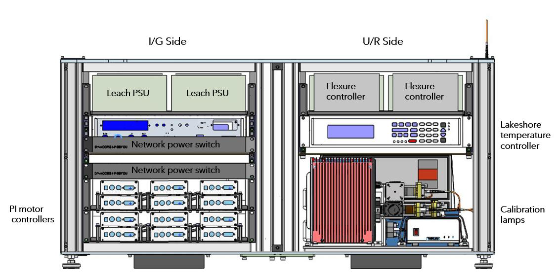
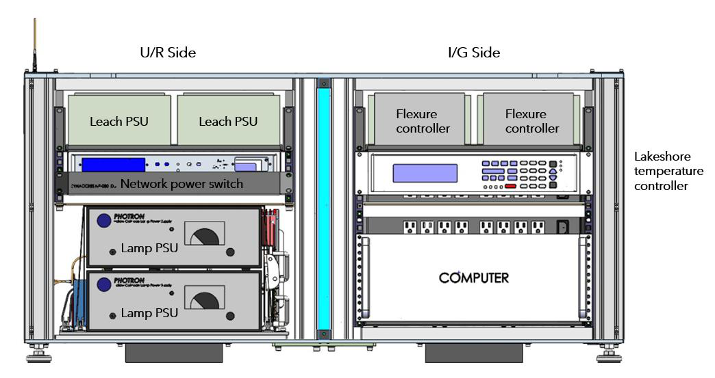
The NGPS electronics cabinet is divided into four quadrants by two internal partitions: a vertical glycol- cooled heat exchanger that splits the rack into two sides; one servicing channels I and G, the other servicing channels U and R. There is also a thin horizontal partition that further divides each side into an upper and lower bay. The four quadrants are ducted into a single airflow loop; fans mounted in the upper and lower bays run in opposite directions, driving a circular flow that passes through the heat exchanger on one pass and returns on the other. The two ends of the rack are left partially open to provide the turnaround paths for this circulation and to route cables between the upper and lower bays.
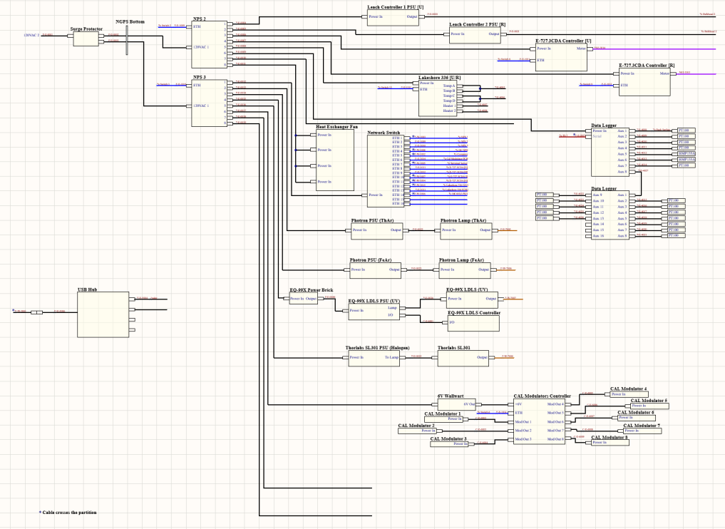
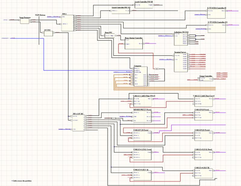
Because the vertical partition physically separates the two halves of the rack, the wiring is documented as two block diagrams, one for the half that services the U and R channels along with the calibration electronics, and another for the I/G channels and motor controllers. Cables that cross the partition between the two sides are marked with an asterisk in both diagrams. A complete inventory of the components shown here, along with their physical locations within the four quadrants, is given in the next section.
Figure 15: Block diagram of the contents of the NGPS electronics rack servicing channels U and R. The full image can be found here.
Figure 16: Block diagram of the contents of the NGPS electronics rack servicing channels I and G. The full image can be found here.
Layout and component list
The half of the electrical rack that services channels I and G contains the instrument computer, the eight- port terminal server, the vacuum gauge controller, and the nine PI motion controllers that drive the A&G filter wheel and dust cover, the I/R/G focus stages, the U-focus stepper, the CAL cover and door, and the two slit mechanisms. The other half of the rack, separated by the vertical partition services channels U and R and contains the calibration light sources (EQ-99X LDLS, the Thorlabs SL301 halogen, and the Photron ThAr and FeAr lamps) along with the calibration modulator PCB controller, the rack’s primary network switch, and the environmental data logger with its PT100 and HMP155A inputs. Several subsystems are mirrored across the vertical partition so that each side carries its own copy: both halves contain two networked power switches (NPS), two Leach detector controller power supplies, two E- 727.3CDA piezo flexure controllers, and two Lakeshore 336 temperature controllers.
Figure 17: E-rack front View.
Figure 18: E-rack rear view.
CAD models of the initial NGPS electronics cabinet layout. Will be updated with labeled photos.