Pre-installation and Mounting#
In-bay preparation and software shutdown#
Between observing runs, NGPS lives in the instrument bay where it is connected to a minimal cable set so that software development and integration testing can continue while the instrument is off the telescope. Before the instrument can be transported to the Cassegrain cage, the software must be brought down cleanly and the bay-side cabling removed. This section covers both steps.
Bay cabling state (typical):
Two 110 V instrument power cords (LF1 and LF2).
One 110 V pressure gauge controller cord.
Two private-network CAT 6 cables.
Not connected in the bay (these are made up only at the Cassegrain cage, see the Cassegrain Cage Power, Network and Cooling Connections page):
Coolant supply and return.
Chiller supervisor cable.
Dry air purge.
Software shutdown (in bay)#
Caution
Do not begin de-cabling until software shutdown is verified. Pulling power or network on a running instrument can corrupt controller state and require recovery work.
Overview
Bring NGPS software down cleanly so the instrument is in a safe, quiesced state before any cables are disconnected and before the hand cart is moved.
NGPS Software Shutdown Procedure (separate document, see Reference Documents)
Procedure
Follow the NGPS Software Shutdown Procedure (separate document) end-to-end.
Confirm all subsystems report shutdown / idle status as defined by that procedure.
Photo references
See NGPS Computer Shutdown Procedure (elab) for the canonical screenshots: (1) Observing GUI with the “Shutdown” button highlighted on the lower right, and (2) the “NGPS is Shutdown” confirmation pop-up.
Verification
Software-shutdown completion confirmed and logged before proceeding to de-cabling.
De-cabling the instrument in the bay#
Caution
Do not skip the walkaround, a forgotten cable will tug or break when the hand cart moves.
Overview
Remove the bay-side cable set so the instrument can be moved to the Cassegrain cage. Only the minimal bay cabling is in place; coolant, chiller supervisor, and dry air purge are not connected at this stage.
Procedure
Confirm the software shutdown above is complete and verified.
Disconnect both LF 110 V instrument power cords (LF1 and LF2) at the bay outlets.
Disconnect the 110 V pressure gauge controller cord at the bay UPS receptacle.
Disconnect both private-network CAT 6 cables.
Coil and stow each cable to travel with the instrument or remain at its bay station per local convention; label any that are not obvious.
Walk around the instrument and confirm there are no remaining bay-side connections (no stray data cables, no power, no fiber, etc.) before releasing hand cart brakes.
Verification
Visual walkaround confirms zero bay-side connections remain.
Common issues
Network cable left behind because it runs along the floor and is easy to miss, explicitly trace each CAT 6 to its switch port.
Pressure gauge controller cord left in the UPS, recheck the UPS receptacle.
Mounting the instrument to the Cassegrain cage#
This section covers the physical mounting of the instrument to the Cassegrain cage. It begins with the instrument staged on its hand cart inside the instrument bay (after the in-bay shutdown and de-cabling above) and ends with the hand cart braked and squared to the floor markings, ready for the lift fixture to engage. The procedure has three steps: transport from the instrument bay to the Cassegrain cage; alignment of the cart to the floor markings; and braking and wheel alignment for the mount.
Caution
Before beginning, verify the telescope is in the correct configuration for an instrument exchange (mirror cover closed, Cassegrain stairs unplugged, floor hoist stowed, HA/Dec pumps shutdown, telescope ring angle set to absolute 184° “GORINGABS 184”).
Starting state of the Cassegrain cage: An instrument was previously on the telescope, so the Cassegrain-cage floor was removed during that de-installation and the floor opening is open at the start of this procedure. Tight clearance through that opening is why caster alignment to the yellow/orange line (see Aligning the cart to the floor markings, below) is critical. The floor is re-installed under the new instrument as part of the closeout (see the final step of Braking, Lifting, and Mounting Instrument to Cassegrain Ring, below).
Transport from the instrument bay to the Cassegrain cage#
Caution
Do not push faster than walking pace. Dome-floor expansion joints and rail crossings can catch casters and cause sudden lurches. Do not use a simple ‘goring’ or ‘gor’ command, use only absolute ‘goringabs’ command.
Overview
Move the instrument on its hand cart from the instrument bay to the Cassegrain-cage rotation area without contacting fixed structures, cables, or personnel.
Procedure
Confirm dome floor is clear along the planned path: no coolant hoses, cables, tools, or personnel.
Release the hand cart caster brakes and rotation locks if engaged.
With two operators on the push handles and a spotter/steerer opposite, carefully exit the instrument bay, checking side clearances. Walk the hand cart along the path toward the Cassegrain-cage station at no more than walking pace.
Stop with instrument near the floor hoist plate with north side of instrument facing north.
Confirm telescope state from TCS: instrument set to NGPS or no instrument; chiller supervisor shut down; mirror cover closed; Cassegrain stairs unplugged and in position at Cassegrain cage door; floor hoist stowed; HA/Dec pumps shut down; Cassegrain ring rotated to 184° absolute (“goringabs 184”) (Figure 19 and Figure 20).
Photo references
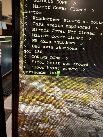
Figure 20#
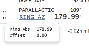
Figure 21#
Common issues
Caster caught on a floor seam or rail, back up an inch and re-approach at a slight angle.
Hand cart drift due to uneven instrument loading, keep the spotter close on the heavy side.
Cassegrain ring in limit and won’t rotate: switch the TCS instrument selection to NGPS or no instrument.
Aligning the cart to the floor markings#
Caution
Cart + instrument is well above 4,000 lb. Minimum three operators. Once moving, the cart has significant momentum, plan stopping distance and communicate verbally before any change in motion.
Overview
Position the cart so the instrument is correctly aligned over the floor hoist plate at the Cassegrain-cage station, using the painted floor markings (orange/yellow alignment lines), the N-S axis reference, the North Desk, and the East/West chock plates. Because the cart and instrument together weigh well over 4,000 lb and clearance to the Cassegrain-cage floor opening is tight, alignment is done in two stages: first the cart is pushed north toward the North Desk to preset the north-side casters in the correct orientation; then the cart is steered south back onto the floor hoist plate for the final position.
Procedure
Identify the NORTH side of the cart (NORTH label) and confirm it matches the dome’s north reference. Brief all three operators on which side is north before moving.
Stage the cart just north of the Cassegrain-cage station, lined up on the N-S axis with the north side of the cart facing the North Desk.
With three operators, push the cart slowly north along the N-S axis toward the North Desk. The purpose of this push is to preset the orientation of the north-side casters, not to land at a final position.
When close to the North Desk, lock the north casters rotation in place with the wheel positioned under the cart, use the fork if necessary (Figure 21).
Now move the cart south, steering from the south and aligning the cart so the inside of each caster is just outside the yellow/orange line (Figure 22).
If the cart is not aligned with the guidelines, it is ok to use a floor jack to correctly position the cart. The cart alignment is crucial to mounting due to low clearance tolerances to the Cassegrain cage floor opening.
Proceed until the cart is on the floor hoist plate, keeping alignment, and stop at the first perpendicular line on the west N/S line (Figure 24).
Set the East and West chock plates (Figure 23) and push the cart back until the casters contact the plates (Figure 25); they prevent the instrument from rolling off the floor hoist plate AND keep the southernmost point of the instrument 5/8” from the Cassegrain cage floor opening frame.
Connect the cart scissor-lift AC power cable to the extendable extension near the south pier (Figure 26).
Final walkaround: confirm the cart is squared on the floor hoist plate, the inside of each caster sits just outside the yellow/orange line, the north casters are locked, and the East/West chocks are in firm contact with the casters before proceeding to the next section. This position will be called position 1.
Photo references
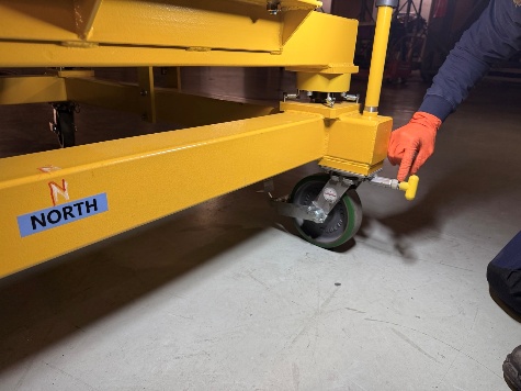
Figure 22#
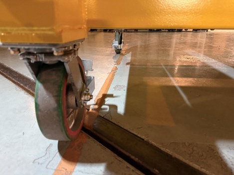
Figure 23#
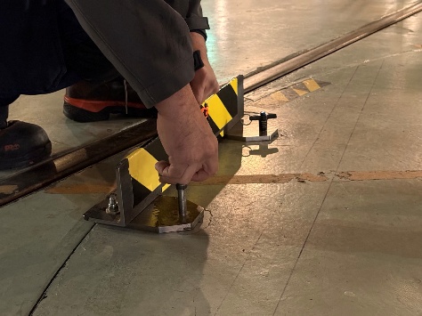
Figure 24#
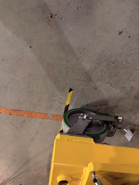
Figure 25#
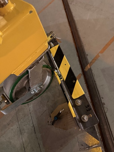
Figure 26#
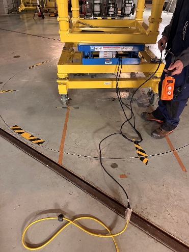
Figure 27#
Verification
Cart sits squared on the floor hoist plate at the first perpendicular line on the west N/S line. Inside of each caster is just outside the yellow/orange alignment line. North casters are locked in the orientation set against the North Desk. East and West chock plates are in firm contact with the casters.
Common issues
North caster not seated correctly when locked at the North Desk, use the heavy fork tool to seat it before locking. A misseated caster will throw off the southward alignment.
The northward preset push fails to orient a caster, use the heavy fork tool to seat it manually rather than re-running the push.
Cart drifts off the N-S axis during either push, stop, re-square on the axis (use the floor jack if needed), and resume. Do not steer under load.
Braking, Lifting, and Mounting Instrument to Cassegrain Ring#
Overview
Lock the hand cart in its aligned position by braking at least one caster. The floor hoist is then used to raise the instrument through the Cassegrain floor. The cart is moved into position 2 for mounting and at the end the instrument is properly mounted to the Cassegrain ring via 4 locking steel aviation posts.
Tools and materials
Scissor-lift on cart, connected to AC power
Important
Minimum 3-person team required to check clearances and push instrument cart into place.
Procedure
With the hand cart in its aligned position 1 from the previous section, engage at least one caster wheel brake.
Remove the thermal sensor cable Amphenol connector from the end of the U-detector dewar (Figure 31).
One person operates the floor hoist and cart lift on the east side of the cart, second person is inside the Cassegrain cage spotting clearances on south and west, third is on the ground spotting north and east/west clearances.
Important
This 3-person team needs to actively communicate during the lift and mount process. Eliminate distractions and interruptions.
With 3 spotters in place and active communication established, begin to raise the floor hoist. All clearances are tight, if at any time a spotter sees a questionable clearance command the hoist operator to stop and only proceed when clear. North clearance (Figure 30). South clearance (Figure 27 and Figure 28). East clearance (Figure 32). West clearance (Figure 29). Lift until the bottom of the south protrusion of the instrument is clear of the Cassegrain cage floor by approximately 2-4 inches (Figure 34), then stop.
Move instrument into position 2: In unison, the ground spotter pushes the instrument from the north, the Cassegrain cage spotter pulls from top of instrument (at the large eye bolts) towards the south and the hoist operator pulls and steers via the south cart posts until the southwest cart wheel is at the position 2 perpendicular line, keeping the cart wheels aligned with the north-south yellow/orange lines.
Remove the south cart posts and stow underneath the instrument (Figure 36).
Remove the east and west float pins and stow them in the spare cutout during mounting (Figure 37).
Now resume spotter positions and raise floor hoist until there is approximately 12 inches from the mounting pins to their seats on the ring, watching clearances on all sides and continuing active communication.
Important
The cart will not fit completely through the floor of the Cassegrain cage, be sure and STOP and watch cart clearance to cage opening (Figure 38).
Use the cart lift for the final lift segment. Lift slowly until mounting pins are close to seats. Work with spotters to float cart for fine tuning pin location to seat and ensure all pins enter simultaneously. Compress cart pistons with lift until the southwest post is at the final marked line (Figure 39).
Lock the clamp wheel; ensure the wheel moves with little resistance clockwise. Count at least 14 turns AND proceed until tight (Figure 40).
Remove the 4 lock pins from the cart.
Move the yellow cooling lines, the network cables and 3 power cables from the cart to the Cassegrain cage floor.
Lower cart lift carefully and watch for any movement at the mount pins. If any downward movement occurs, raise the cart lift and repeat Step 10. If still in doubt, call the supervisor.
If all clear, lower cart lift completely and then lower floor hoist and uninstall east/west stops from hoist plate and place on cart. Unplug cart lift power and retract power cable, stow lift controller and AC cord on cart. Stow the cart near the aluminization cart until uninstall.
Replace Cassegrain floor per normal procedure and proceed to the next section.
Photo references
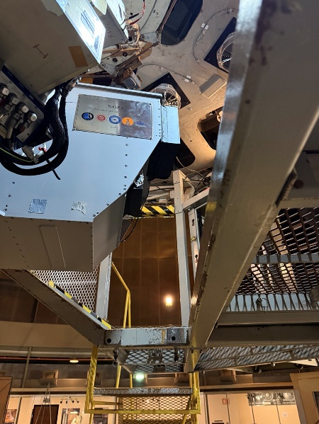
Figure 28#
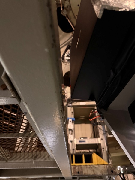
Figure 29#
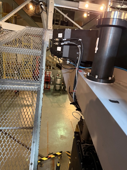
Figure 30#
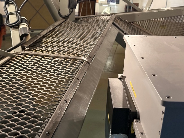
Figure 31#
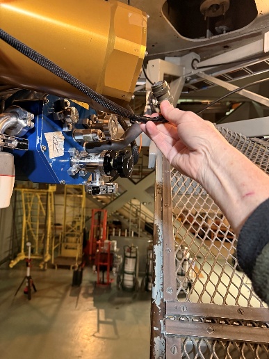
Figure 32#
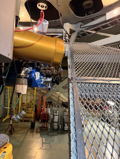
Figure 33#
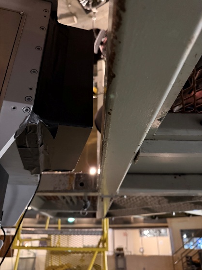
Figure 34#
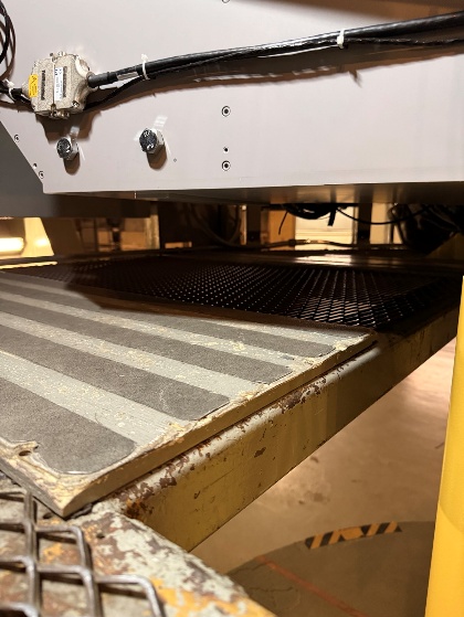
Figure 35#
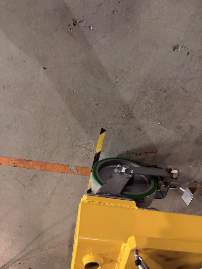
Figure 36#
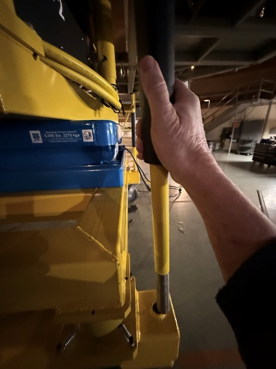
Figure 37#
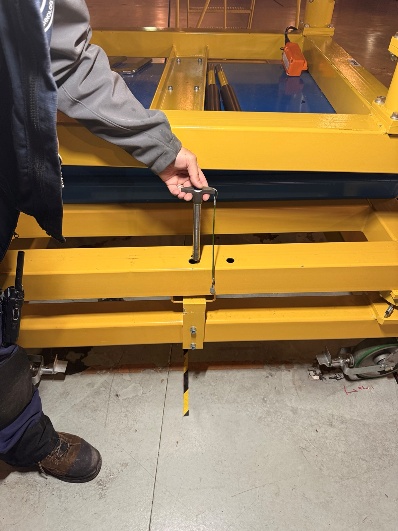
Figure 38#
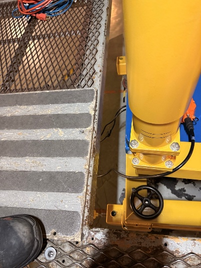
Figure 39#
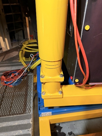
Figure 40#
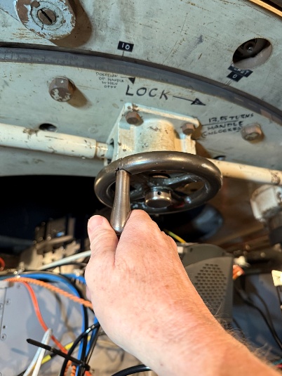
Figure 41#
Verification
All four caster brakes visibly engaged; floor anchor (if used) seated and snug; wheels parallel to frame.
Common issues
One brake engaged but the lever did not click into detent, re-engage and verify with a tug-test on the hand cart.