Cassegrain Cage Power, Network and Cooling Connections#
With the instrument mounted and the Cassegrain-cage floor re-installed under the new instrument, the rest of the install (cabling, fluids, balance) happens from inside the cage.
Coolant lines and dry air purge#
Caution
Quick-connects retain residual coolant, drip tray and absorbent pad ready, and wipe the mating face before engagement. Do not start the chiller (see Data Room) until both NGPS valves are confirmed open and the connections are verified.
Overview
Connect the chiller’s yellow coolant supply and return lines from the instrument to the west-side Cassegrain cage manifold. Connect the dry air purge to NGPS. Route these lines together inside the yellow-jacket cable guide AND keep the coil direction of the lines the same as when cooling lines were stowed so instrument rotation will uncoil correctly (i.e. coiling with CW rotation, uncoiling with CCW rotation).
Tools and materials
Yellow coolant supply and return lines (Figure 41) (from NGPS to Cassegrain cage manifold)
Black dry air purge (from Cassegrain cage to bottom of NGPS)
Procedure
Route the yellow coolant supply and return lines inside the open yellow-jacket cable guide on the Cassegrain cage floor with enough slack to connect to the manifold.
Mate the supply and return quick-connects at the manifold on the west side of the Cassegrain cage. Confirm each fitting seat with an audible/tactile detent click and the locking sleeve has returned to its forward position (Figure 42).
Route the dry air line from the Cassegrain cage inside the cable guide and alongside the coolant lines, secured with Velcro.
Remove the protective caps on the air purge line and connect at coupling.
Important
Guard against any debris entering the line, this is a direct path to the detector.
Check flow rate is set at 35 liters per minute.
Visual leak check at both quick-connects, no drips, no weeping at the fittings, no kinks at the strain-relief radius.
Photo references
The two photos below show the coolant manifold connections at the Cassegrain cage.
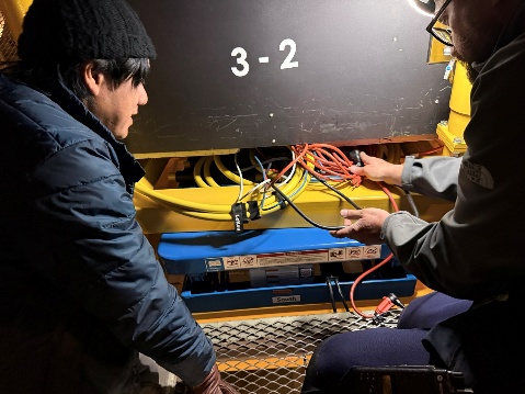
Figure 42#
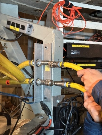
Figure 43#
Verification
Both supply and return quick-connects fully seated; both NGPS valves open; lines dressed with adequate strain-relief radius; no visible leaks.
Common issues
Quick-connect not fully seated, listen and feel for the detent click; verify the locking sleeve has returned to its forward position.
Supply and return cross-connected, verify labels at the manifold before mating; flow direction matters for the chiller.
Coil radius too tight, leads to kinking on rotation; re-dress with a wider radius.
Instrument power, LF1 and LF2#
Overview
Provide 110 V to both NGPS NPS power switches on the instrument from the dedicated “Instrument 1” outlets at the Cassegrain cage.
Tools and materials
Provided LF1 and LF2 instrument power cords
Procedure
Plug LF1 into “Instrument 1” outlet A (CKT 16A) at the Cassegrain cage (Figure 44).
Plug LF2 into “Instrument 1” outlet B (CKT 16B) (Figure 44).
Confirm the female 110 V plugs at the rear of each NPS on the instrument are firmly seated, tug-test each plug, do not rely on visual seating alone.
Photo references
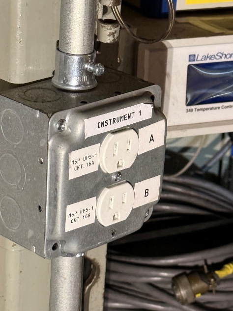
Figure 44#
Verification
Both NPS units power up and reach the network. Confirm via the NPS web interface.
Pressure gauge controller power#
Overview
Power the vacuum pressure gauge controller from the Cassegrain cage UPS so vacuum monitoring continues across power events.
Procedure
Plug the pressure gauge controller 110 V cord into the Cassegrain cage UPS receptacle.
Verification
Pressure controller boots and reports both gauge channels via the NGPS pressure dashboard (http://10.200.71.52/ngps/).
Private network connections and Chiller Supervisor Cable#
Overview
Connect the instrument’s two CAT 6 network drops to the NGPS private network AND the chiller supervisor signal cable so the control system, NPS units, pressure logger, and chiller supervisor are all reachable.
Procedure
Connect both CAT 6 cables from the instrument to private-network switch ports.
Connect the chiller supervisor signal cable from the Cassegrain cage to the receptacle on the bottom of the instrument. Note: you may need to remove the cable from the P3K Cassegrain Rack (Cass 1).
Route the chiller supervisor cable from the Cassegrain cage through the cable guide alongside the coolant lines. Secure with the Velcro already attached to the coolant lines.
Check inside the chiller manifold cabinet that the NGPS valve is open.
Photo references
The photos below show the private-network and chiller supervisor connections at the instrument and Cassegrain cage.
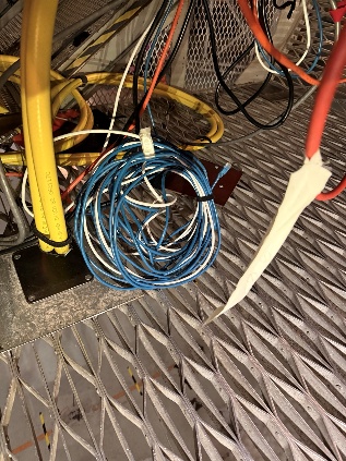
Figure 45#
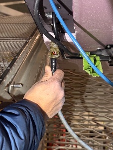
Figure 46#
Verification
Verify that thermal data is displayed in Grafana (http://10.200.129.161:6502/login) and that pressure data appears on the NGPS pressure page (http://10.200.71.52/ngps/).
Cable dressing and yellow-jacket cable tray#
Overview
Bundle, suspend cables in center under instrument with plenty of slack for rotation, and capture all Cassegrain-cage-side cables in the yellow-jacket tray so no cable carries strain at its connector.
Tools and materials
Velcro straps
Bungie cords (for yellow-jacket tray closure)
Procedure
Bundle the cables and suspend the bundle from the bottom center of the instrument so no cable carries strain at any connector (Figure 46).
Coil any slack with an adequate radius so the bundle does not kink as the Cassegrain ring rotates.
Velcro the bundle along the Cassegrain cage floorboard so it travels predictably with the cage.
Run the dressed bundle inside the yellow-jacket cable tray and close the tray with bungie cords. Inspect bungies for cracked rubber or worn hooks; replace any in poor condition.
Photo references
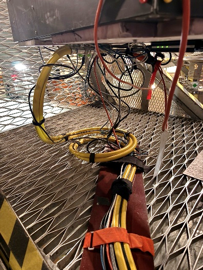
Figure 47#
Verification
No cable carries strain at any connector. Bundle inside yellow-jacket tray. Bungies engaged and intact.
Common issues
Coil diameter too small, strains conductors on rotation; re-dress with a wider radius.
Bundle resting on a sharp edge, abrasion risk; re-route or add padding.