Acquisition, Calibration, and Slice Viewing Hardware
Acquisition and Guidance System
The acquisition and guidance system is an imager (offset approximately 8’) from the spectrograph optical axis. It has its own enclosure with a dedicated hatch (currently broken). A fold mirror redirects the light horizontally through a field lens and, subsequently, a fixed focusing lens. In the backfocal space between the lens and camera is a filter wheel with 6 positions. These are populated with 50 mm diameter filters: (g’, r’, I, blocking, clear, and empty). The clear filter is an AR coated piece of glass that maintains the same focus as the color filters.
The camera was shimmed in lab to be confocal with the image slicer. There is no focus adjustment on this camera.
Both the filter wheel and the hatch are custom mechanisms, but both are driven by PI C-663.12 controllers. The hatch has an ST2818M0704-G2 stepper motor and JK8002C hall effect limit switches. The filter wheel also uses an ST2818M0704-G2 stepper motor and a JK8002C hall effect home switch. The A&G electronics are further detailed in the Electronic control instructions for NGPS A&G system document.
There are two cover panels on top of the A&G system. One of the panels has the hatch attached to it and there are wires installed on the underside. While this panel can be unbolted and lifted, care needs to be exercised when doing so to avoid accidentally stretching the conductors. There is no internal disconnect to completely free this panel. The other panel, that immediately above the camera and filter wheel, can be easily removed.
The A&G system is served by the acam daemon and the ACAM GUI.
Calibration Unit
Overview
The calibration unit provides the light sources and means to illuminate the NGPS slicer with light needed for spectral and flat-field calibration. The optics are designed to mimic the Hale Telescope f/16 focal ratio.
The calibration system is composed of two sections.
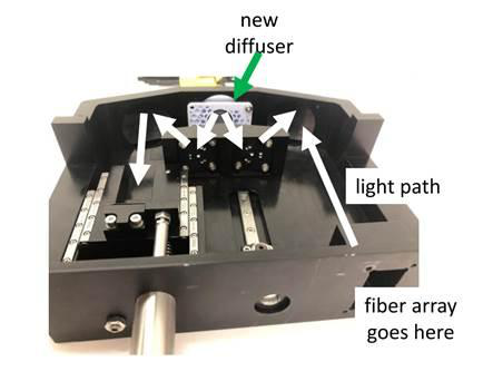
The first is a reimaging unit that is mounted on the NGPS slicer assembly. That contains an entrance aperture equipped with a light-blocking door, reimaging optics and diffuser. This section also includes the actuated instrument cover. The terms ‘door’ and ‘cover’ here are deliberate, and explicitly identify the actuator in the instrument control software. We recommend the instrument cover be closed whenever the instrument is not in use. Both axes are driven by PI L-220.50DG high-resolution linear actuators commanded by PI C-863.12 controllers.
Figure 14: Alos Blort.
The second is the calibration shelf in the electronics cabinet. This contains the light sources, their power supplies, and shutters.
INCLUDE (ROUGHLY) LABELED PHOTO OF CALIBRATION UNIT SHELF Figure XX
The two components are connected by an optical fiber harness (an octopus). Each lamp has a single multimode fiber attached to it. The continuum lamp paths then travel through adjustable fiber attenuators. The parallel paths then continue to a MIXING DEVICE, and terminate at the calibration box near the focal plane.
INCLUDE DIAGRAM OF CAL LIGHT PATH Figure XX
Note that the instrument hatch is actually part of the calibration enclosure and is controlled by the calibd software daemon.
The calibration system is served by the calibd daemon
Spectral Calibration Sources
NGPS uses thorium argon (ThAr) and iron argon (FeAr) hollow cathode arc lamps. Each is in its own enclosure and is powered a dedicated Photron P209-USB power supply.
The current (Apr 2026) ThAr lamp is a: Green Scientific G858A hollow cathode lamp The current (Apr 2026) FeAr lamp is a: Photron P826A hollow cathode lamp
Notes:
It is enough to turn the power on to the two lamps for them to turn on. There are rocker switches on the photron supplies if power needs to be cut locally.
Lifetime of the lamps varies a bit and depends on the implementation, usage details, etc. We anticipate a lifetime of about 2 years. The lamp enclosures are designed to be serviceable with the removal of just one of the four electronics cabinet covers (cover X-X)
ThAr lamps (as of this writing, Apr 2026) are somewhat difficult to source.
INCLUDE A ZOOM ON THE TWO LAMP BOXES INCLUDE PHOTO OF A BULB Figure XX
Flatfield Calibration Sources
NGPS has two continuum sources. A tungsten-halogen lamp (Red lamp) from Thorlabs (model #SLS301) and Enegetiq Laser Line Source (Blue lamp, model #EQ-99X LDLS). Each lamp has beam splitter optics at the front that separate the light path to a direct and sent part of the light through an etalon. The etalon produces a periodic spectrum, whereas the direct path is a clean continuum. The two paths each have an independent shutter.
The lamps also have dDichroic beam splitters for their spectra to interleave.
We have also implemented, but do not currently use, optical paths for the continuum lamp light to pass through etalons generating periodic spectra. The intent was to use these spectra for concurrent calibration (light injected via optics-coupled fibers at the edges of the slit and slices). The functionality is available, and we may implement this in the future.
Notes:
The Red continuum lamp turns on when the appropriate outlet in the NPS is powered. There is a rocker switch on its enclosure to cut power locally.
The blue continuum lamp needs an interlock to turn on. There is a control box with NGPS equipment in the instrument bay. We have implemented, but not yet deployed computer control of this lamp. More information can be found here.
Unfortunately, the calibration system optical throughput is very low at wavelengths shorter than about 350 nm (due to mirror coatings and multiple reflections, most likely), so the utility of the Blue lamp is limited. As of Apr 2026, we have procured some bright UV LEDs and will attempt to construct a pseudo- continuum source to overcome the reduced throughput. This work is ongoing.
The short-pass filter installed in the Blue lamp has some leak that can be seen in the R and I channel data.
Blue Lamp images To Be Added Figure XX
Red Lamp images To Be Added Figure XX
Blue Lamp leak images To Be Added Figure XX
Calibration Shutters (AKA Modulators)
There are 6 modulators installed in the calibration system, one per lamp. The assignment is shown in the table below. These can function as bona-fide shutters, or to limit the lamp duty cycle mechanically. These modulators are Takano BOS10-15 bi-stable rotary optical shutters and are controlled by an Arduino Teensy 4.1. The arduino embedded code (NGPS_Mods_V006_quiet.ino) can be found here (in SharePoint > NGPS - Subsystems [L3] > Electronics Rack [EL] > Electronics Rack -TECs > Calibration Lamps > Modulators ).
Notes:
The modulators are very sensitive to the mounting torque of the screws that hold them in place. Best to have these operating as you install, if possible.
One of the modulators (#2, for blue continuum etalon). is sticky; it is rarely, if ever, used.
Modulator # Lamp
Taking a calibration image
Users should not need to do this, but it is included here for engineering purposes:
Ensure shutter is enabled in camerad and appropriate exposure time is set
Close the instrument cover
Open the calibration door
Open the modulator for the appropriate lamp
Turn on the appropriate lamp
Slice Viewing System
There are two Andor iXon Ultra 888 EMCCD cameras that pick off the telescope field. The cameras have FOVs of approximately 60” x 30” and plate scale of XX. The fields are adjacent to the outer two slices and, as such, shift as the slit width is adjusted.
The cameras are controlled via the SLICEVIEW GUI. The GUI is intended primarily for field alignment and some field recognition.
Currently, the cameras operate in classical (gain=1) CCD mode. Employing the available EMCCD mode to improve sensitivity is possible, and is a future feature.