Instrument Hardware Overview
Figure 3: A block diagram of NGPS showing the light path and principal components of the NGPS system. A brief summary of each (and several others that are not pictured) is presented below, with more detailed descriptions following in subsequent sections.
Structure Partial exoskeleton of the NGPS optics, and instrument mechanisms. Serves as the mounting for the detector cryostats, calibration system, slicer assembly, A&G system, and electronics. Provides the mechanical interface to the P200 Cass rotator
Instrument hatch A small door immediately above the slicer/science FOV. Doubles as the mount for the folding mirror that redirects calibration light into the NGPS optical path.
Slicer/slit unit Collects desired target light while blocking unwanted sky and stray light, contributes to the spectral resolution. The slicer unit relays the telescope focal plane to a reformatted slit plane. Includes mechanism for variable selection of the slit and slice width.
Shutter The shutter mechanisms controls the exposure length and light impinging upon the detectors. A single shutter is used for all detectors imparting on the detector controller certain synchronization requirements.
DDichroic tree Optical assembly containing three dDichroic beam splitters and a mirror that performs spectral separation and folds beam horizontally.
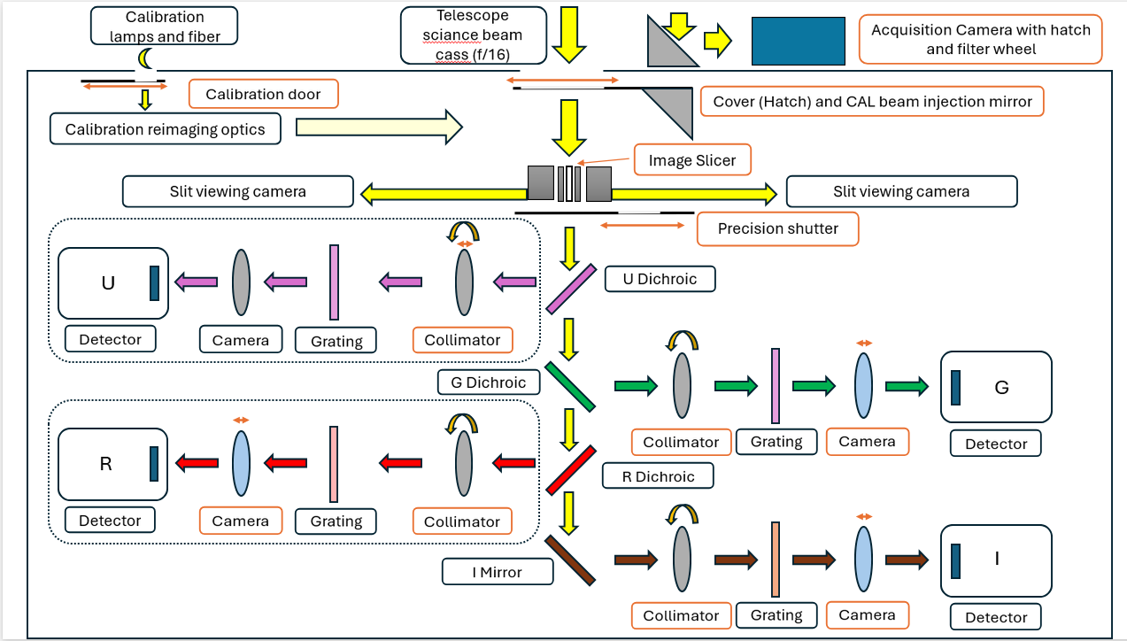
Collimator(s) Forms a pupil on the grating where a mask blocks light originating outside telescope beam; piezo actuated for flexure compensation in dispersion direction. Also includes the focus axis for the U channel.
Diffraction grating(s) Transmissive diffraction gratings disperse the light in the spectral direction
Camera(s) Refocuses the dispersed light onto the detector(s). For three channels (G,R, and I) also includes focus mechanism
Detector(s) Converts optical signals for target and sky into electrical signals; includes cryostat subsystem to maintain cold, dry operation of the science CCDs.
Acquisition and Guiding (A&G) subsystem Determines initial telescope pointing, commands telescope to move so that desired target is correctly positioned on the slicer/slit, then continuously updates pointing correction.
Slice viewing subsystem Provides visual confirmation of the alignment between target and slicer/slit; user may respond by invoking manual pointing offset.
Instrument electronics Provide a means to control and monitor instrument, it’s performance and health. Housed in a dedicated electronics cabinet attached to the underside of the structure.
Calibration unit Provides wavelength calibration light sources. Includes a mechanism to select instrument input between telescope output and calibration unit output. Includes continuum sources for flat fielding.
Ground support equipment (GSE) Necessary for instrument operation, including an instrument handling cart, shipping containers, and maintenance supplies.
Instrument control software Provides both manual and automated observing modes; interfaces to the TCS; commands internal mechanisms; executes instrument automations; presents images from A&G, slice viewers, and spectroscopic detectors; provides ‘quick look’ plots to human observers.
Data reduction pipeline Performs bias correction, flat fielding, wavelength calibration, sky subtraction, and spectral extraction. Provides the user with object, variance, and sky spectra. Performs flux calibration if the user provides observations of a flux standard.
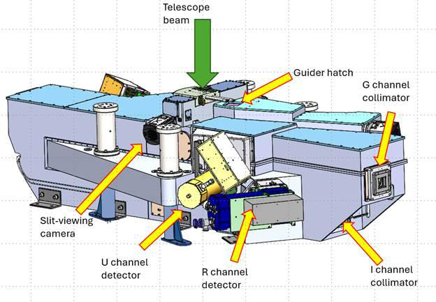
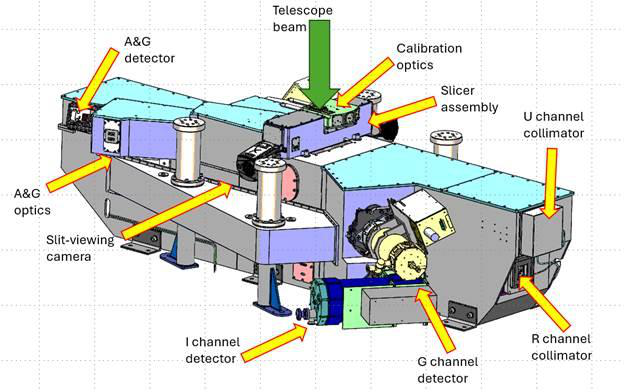
Figure 4: Main instrument body with key components visible from the outside highlighted.