Optical Path
Slicer Assembly
The slicer assembly is mounted to the top of the instrument (see Figure 1). The calibration optics subsystem is mounted to its top and the instrument shutter is attached to its underside. A detailed write-up of the design can be found in the NGPS document repository.
The slicer assembly houses the slicer optics and mechanism, slit reimaging optics, and slit reimaging cameras.
The principal function of the slicer assembly is to reimage a ~60” x (3Z)” field on sky into a ~ 180” x Z” slit entrance slit to the subsequent classical spectrograph optical system.
The slicer assembly has two linear actuators that each drive a group of three reflecting prisms. The actuators are PI M-230.10 controlled by PI C-863.12. The actuators need to be homed whenever their controllers lose power. The nightly shutdown procedure leaves them powered so that startup is quicker on subsequent nights.
Two of the prisms form NGPS’s adjustable slit. We are limiting the adjustment from 0.36” to 10” on sky. The 0.36” slit width corresponds to a physical separation of about 0.14 mm. A configurable software limit prevents operation outside this range. There is very little margin from our minimum setting to where the two jaws come into contact. The mechanism was designed so the contact points are robust and independent of the fragile optics, protecting those from damage. However, once in contact, the stepper motors may skip steps, losing their position, and any subsequent slicer reconfiguration (width or offset), cannot be trusted.
Fabrication of the slicer and other associated reflective prisms was an adventure. Vendor had trouble hitting specifications and so the final optomechanical assembly is not optimal. One of the main issues is streaking in continuum spectra of the central slit due to non-uniformities in slit-jaw edges. This streaking is most evident for narrowest slits. We also see reduced slit-length and light loss in the outside slices due to vignetting in the relay optics.
ADD FIGURE FOR SLIT STREAKING
Shutter
NGPS is equipped with a single exposure controlling shutter. It is a 23 mm x 90 mm Bonn- Shutter and its manual can be found on the NGPS site (Bonn-Shutter Manual). The unit is mounted to the underside of the slicer box atop the NGPS structure. In the optical path it is after the slicer, but before the dDichroic tree. Telescope light can reach the slicer and slit viewing cameras without being let through to the science cameras. The shutter controller is mounted in the electronics rack. The trigger signal for the camera is delivered via a TTL line controlled by the camera software. The camera software also includes a provision to disable shutter actuation during an exposure (useful for biases, dark exposures,…)
The shutter is a two-blade design that relies on careful timing of the two stepper motors driving the sliding blades for timing precision. This results in a shutter that allows spatially uniform and very short (< 100 ms) exposures without the need for very fast moving parts.
Installation note: the design called for mounting the shutter with 4 screws, but we found that that warped the mechanism and prevented proper operation. We removed one of the screws to achieve proper function. The shutter is attached to the underside of the slicer enclosure and, as such, requires the removal of the slicer enclosure when servicing or replacing.
DDichroic Tree
The dDichroic tree is nestled under the slicer and instrument shutter. Dichroic beam-splitters separate the science light into four wavebands. Total bandwidth matching the 310-1040 nm accessible from the ground with silicon detectors is split at 430, 584, and 781nm. These splits are chosen to be approximately equal in the ratio of spectral bandwidth to center wavelength, an arrangement that best matches the efficiency of the diffraction gratings. These splits are achieved using long pass filters for U, G, and R, and a mirror for I. The fused silica filter substates are slightly wedged to reduce astigmatism in the transmitted beam. Coating curves with a zoom on the transition region between channels are presented below. Much more detailed information can be found on the NGPS Sharepoint: DDichroic tree directory: DDichroic Tree [DCH] Subsystem delivery report: NGPS.DCH.TEC.010.xlsx Coating data: NGPS.DCH.TEC.009.xlsx Detailed design note: NGPS.DCH.TEC.006.doc
Figure 5: The dDichroic tree as designed. The mirrors direct the light at 90deg relative to the telescope axis, allowing the convenient linear design for the instrument. The dDichroic mirrors are arranged sequentially in wavelength, maximizing efficiency at shorter wavelengths.
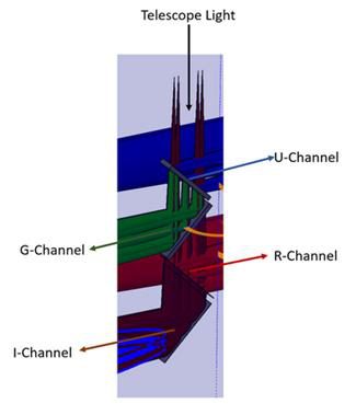
Figure 6: Transmission curve (in %) for the NGPS U Channel dDichroic. Bottom panel zooms in on the transition region. Very little light is lost to absorption, so the reflected
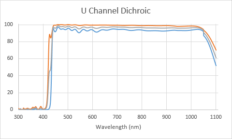
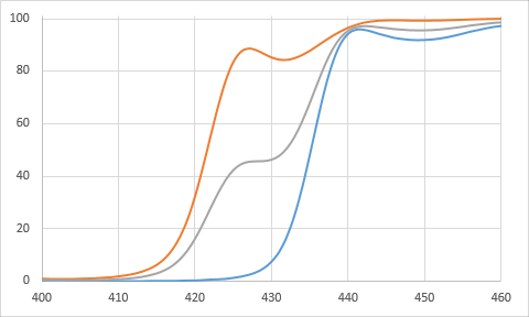
Figure 7: Transmission curve (in %) for the NGPS G Channel dDichroic.
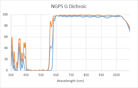
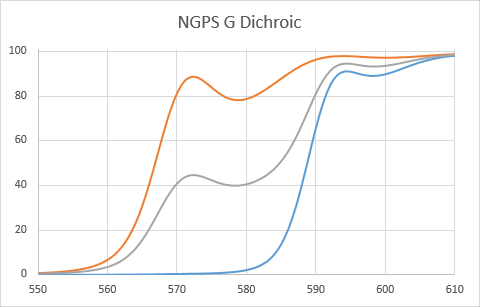
Figure 8: Transmission curve (in %) for the NGPS R Channel dDichroic.
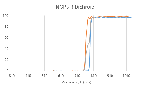
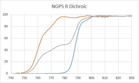
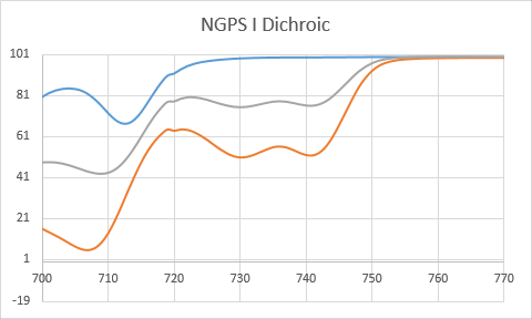
Figure 9: Reflection curve (in %) for the NGPS I Channel mirror.

Note that in addition to the wavelength filtering coating on the first surface of each optic, the rear of each is coated with an anti-reflection (AR) coating. That AR coating is generally tuned to the transmitted bandpass and so its performance is not as good out-of-band. The consequence is that at the dDichroic cross-over regions we may encounter faint ghost spectra that are close to in-focus. Due to the wedges in the substrates these are offset from the real images by a few (2-3) mm in the spatial direction.
Collimators
Each of the four channels has its own collimator, all with a concave radius of R = 3140 mm and a rectangular aperture 100x180 mm. The substrates are Schott Zerodur. Coatings have been optimized to suit the channel on each mirror. The G, R, and I collimators are coated with enhanced silver. The U optic has a multilayer-dielectric coating.
The collimator optics are described in more detail in the spectrograph section of the NGPS sharepoint. NGPS-SPC.TEC.023 ,in particular, may be of interest.
Figure 10: Design coating curves for the 4 NGPS collimators. AS-COATED CUVES SOMEWHERE?
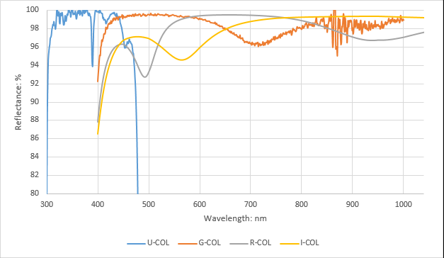
Figure 11: U collimator on the left, one of G/R/I collimators on the right.
All four of the collimators are mounted to precision piezo tip/tilt/piston. The stages are the PI P-528.TCD and their controllers are installed in the electronics cabinet. The servos are tuned using PI’s PIMikroMove software (Windows) with the controller connected to a lab computer via a USB cable. For convenience, USB cables from the 4 controllers have been brough out through the cable grommets at the top of the electronics cabinet. An overview of the tuning process and results can be found here.
Optically, approximately 21 counts (21 urad tilt TBC) corresponds to a single detector pixel shift.
U Channel Focus
The U channel has a different focus solution to the G, R, and I channels. See Section XXX for that.
The U collimator is mounted to a linear stage equipped with limit switches and a power-off break. The stage is a Shinano Kenshi STP-28D3003 with a 24V active high motor lock and the limit switches are JK8002C hall sensors. The wiring diagram is shown in NGPS.EL.TEC.001.docx. The stage is driven by a Galil DMC-30016-BOX(SER,MO)-(HSRC) motion controller.
The stage is homed against the reverse limit switch (that is defined as position 0). The forward limit switch is at 15,800 (TBC) while best focus is around 12,500 (TBC) Approximately 420 (TBC) counts correspond to 1 mm of motion of the collimator which, in turn, corresponds to about 40 (TBC) um of focus change at the detector.
Diffraction Gratings
Each channel has its own Volume Phase Holographic (VPH) diffraction grating. The inspection reports for the 4 gratings can be found in the Wasatch VPHs directory of the NGPS document drive. The gratings are located at the reimaged telescope exit pupil (reimaged by the collimator) and are just upstream of the channel cameras. Figure XX below shows the vendor measured efficiencies for the 4 optics.
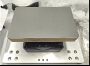
Figure 12: Vendor measured 1st order diffraction efficiencies for the four NGPS gratings. Different curves for the same grating correspond to different sub-apertures.
Grating Operating Wavelengths (nm) Fringe Frequency (l/mm)
U 310 - 440 1300
G 400 - 625 938
R 560 – 800 695
I 750 - 1040 600
The U and G channel gratings are visible and accessible through the large panels on top of the instrument. The R and I channel gratings are accessible through small panels on the underside of the instrument. The underside gratings are difficult to access.
The gratings were not intended to be easily adjustable, so any future tweaks require substantial planning.