FITS Header Keywords
Science
Keywords in the following tables are included in the FITS headers for the spectrograph science images. Keywords in table xx are added to the primary header; keywords in table xx are added to each additional image extension header.
Table 5: FITS Primary Header Keywords
Keyword Description BZERO offset for signed short integers BSCALE scaling factor INSTRUME Name of instrument (NGPS) FILENAME this filename OBJECT target name IMGTYPE Type of image (bias, flat_internal, flat_dome, etalon, arc, science, standard)
EXPTIME exposure time in milliseconds SHUTTIME actual shutter open time in milliseconds EXPSTART exposure start time YYYY-MM-DDTHH:MM:SS.sss MJD0 exposure start time (modified Julian date) MJD1 exposure stop time (modified Julian date) MJD Average of MJD0 and MJD1 DATE FITS file write time YYYY-MM-DDTHH:MM:SS.sss BINSPECT binning in spectral direction BINSPAT binning in spatial direction SLIT slit width in mm CASANGLE TCS reported Cassegrain angle in deg LAMPS Info on which lamps are on, arcs, etalon AIRMASS0 TCS reported airmass at start of exposure AIRMASS1 TCS reported airmass at end of exposure AIRMASS Average of AIRMASS0 and AIRMASS1 HA hour angle RA Requested right ascension in J2000 DEC Requested declination in J2000 RAOFFS offset right ascension DECOFFS offset declination TELRA TCS reported right ascension TELDEC TCS reported declination AZIMUTH TCS reported azimuth ELEVATIO TCS reported elevation DOMEAZ TCS reported dome azimuth TELESCOP Name of telescope (P200) OBSLON Observatory longitude (-116.8583299 ) OBSLAT Observatory latitude (33.353498586) DOMESTAT Dome shutters 1=open 0=closed TEMPTURE Which? From where? WINDSPD From where? WINDDIR From where? DEWPOINT From where? WETNESS From where? HUMIDITY From where? PRESSURE From where? CLOUDS From where? CCDTEMPU CCDTEMPG
CCDTEMPR CCDTEMPI
Table 6: FITS secondary image extension keywords (applies to each image extension)
Keyword Description BITPIX number of bits per data pixel NAXIS number of data axes NAXIS1 length of data axis 1 NAXIS2 length of data axis 2 EXTNAME extension name { U G I R } FIRMWARE detector controller firmware file FIRM_MD5 MD5 checksum of detector controller firmware DEV_ID detector controller device ID { 0, 1, 2, 3 } SPEC_ID Spectrograph channel { U, G, R, I } CCD_ID CCD Identifier (e.g., serial number or similar identifier) AMP_ID CCD amplifier ID {U1,U2, L1, L2} VID_ID Leach video out {0, 1, 2, 3} SPECPART Which part of this channel’s spectrum {BLUE, RED, WHOLE} READMODE Code describing how image is read (frame transfer, split, which amps)
ACAM
Table 7: FITS keywords for acquisition & Guide Camera images.
Keyword Description BITPIX number of bits per pixel NAXIS1 number of data axes INSTRUME Name of instrument (NGPS) NAME target name EXPTIME exposure time in seconds EXPSTART exposure start time YYYY-MM-DDTHH:MM:SS.sss MJD0 exposure start time (modified Julian date) CASANGLE TCS reported Cassegrain angle in deg AIRMASS TCS reported airmass at start of exposure RA ACAM center right ascension in J2000 (string format) TELDEC ACAM center declination in J2000 (string format)
RAOFFS offset right ascension DECOFFS offset declination TELRA TCS reported right ascension TELDEC TCS reported declination AZIMUTH TCS reported azimuth ELEVATIO TCS reported elevation FILTER ACAM filter GAIN (e-/ADU) ; has some value even if using EM gain SATURATE Pixel value considered saturated HBIN Horizonal binning VBIN Vertical binning TELFOCUS Focus position of telescope RADESYSa ‘FK5” ; Telescope pointing system type WCSAXES “2” ; number of axes in WCS description CRVAL1/2 reference coordinate (deg) CRPIX1/2 reference pixel CUNIT1/2 “deg” ; units of CRVAL and CDELT CTYPE1 “RA—TAN” (3 dashes) ; projection type CTYPE2 “DEC–TAN” (2 dashes) ; projection type PCi_j i=1, 2 ; j=1,2 ; rotation matrix element CDELT1/2 pixel scale along axis PIXSCALE Arcsec/pixel (nominally 0.26) POSANG Angle of image Y-axis relative to North
Slice Cameras
Table 8: FITS keywords for Slice Cameras
Keyword Description
SLICE_ID Some identifier for which camera e.g. A or B
BZERO offset for signed short integers
BSCALE scaling factor
INSTRUME Name of instrument (NGPS-SLIT)
OBJECT target name
EXPTIME exposure time in milliseconds
TEXPTIME Total exposure time of image stack
EXPSTART exposure start time YYYY-MM-DDTHH:MM:SS.sss
MJD0 exposure start time (modified Julian date)
CASANGLE TCS reported Cassegrain angle in deg
AIRMASS0 TCS reported airmass at start of exposure
RAOFFS offset right ascension
DECOFFS offset declination
TELRA TCS reported right ascension
TELDEC TCS reported declination
AZIMUTH TCS reported azimuth
ELEVATIO TCS reported elevation
GAIN (e-/ADU) ; has numeric value even if using EM gain
SATURATE Pixel value considered saturated
HBIN Horizonal binning
VBIN Vertical binning
TELFOCUS Focus position of telescope
PIXSCALE Arcsec/pixel
POSANG Angle of image Y-axis relative to North
Generating WCS Headers
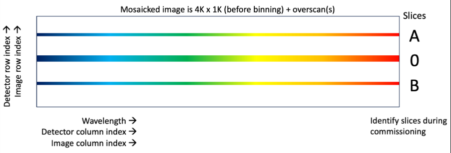
All images are being deinterlaced and stored such that bluest wavelengths are on the left and slice #A (to be defined during commissioning) is at the top. There will be overscan regions on some image borders depending on which amp(s) is used to read out. We will identify X or Y as being “spectral” or “spatial” since different detectors will have different parallel/serial orientations relative to the image.
Figure 19: Mosaicked image.
Definitions:
L = 1 if overscan region on image left, 0 if not
B = 1 if overscan region on image bottom, 0 if not
OSPAT = number of overscan pixels in the Y (spatial) direction
OSPEC = number of overscan pixels in the X (spectral) direction
DETSIZEX = number of physical detector pixels in the X (spectral) direction
DETSIZEY = number of physical detector pixels in the Y (spatial) direction
Physical Headers
To account for offsets between the image pixels and the physical pixels of the detector we use LTV1 and LTV2 (X and Y linear translation vectors). The lower left corner of any image will always be (1,1) in DS9 image coordinates. These headers will change the detector coordinate fields.
LTV2 = B*OSPAT/BINSPAT
LTV1 = L*OSPEC / BINSPECT (1 amp or blue side)
LTV1 = [OSPEC – DETSIZEX/2]/ BINSPECT (Red side)
E.g. for split X, the red side of the detector starts at column 2048. Overscan would be on the left side of that image. If it has 100 columns of overscan, LTV1=100-2048=-1948 i.e. we are saying that to align the detector with the image, we’d place the physical edge of the detector 1948 cols off the left side of the image. There are also headers to convert image pixels to spectral/spatial positions. Each channel will have its own wavelength offsets and dispersion scale:
Minimum wavelength
Dispersion
(Å)
(Å/px)
U 3200 0.31 TBC
G 4170 0.42 TBC
R 5610 0.576 TBC
I 7560 0.71 TBC
The following headers will be the same for all amps in all channels: WCSNAMEA = ‘SPECTRUM’ // CUNIT1A = ‘Angstrom’ // Dispersion units CUNIT2A = ‘arcsec’ // Spatial units CDELT2A = .191 * BINSPAT // [arcsec/pixel] Spatial scale CRVAL2A = 0. // [arcsec] Reference value
The following headers will be the same for all amps in a channel. Example for channel R: CDELT1A = .576 * BINSPECT // [Å/pixel] Dispersion CRVAL1A = 5610. // [Å] Reference value
To arrange the images, it is somewhat simpler to locate/compute the pixels (CRPIX) that would match a common physical origin (CRVAL) rather than select a reference pixel for each image and compute the CRVALs there. We can use the LTVs for this, keeping in mind they depend on the amps used.
CRPIX1A = LTV1 + 1
CRPIX2A = LTV2 + 1
Display Headers
These headers are for mosaicking multiple amps and detectors into a diagnostic display. Unlike the physical headers, we’re now arranging images from multiple detectors. Detectors have overlapping wavelength ranges,
and images may include overscan, so mosaicking all images with all pixels visible is convenient but the exact placement has less physical meaning.
Let’s say we want to organize channels descending vertically as (U, G, R, I). GAPY = 20 (adjust to taste) CRPIX1 = 0 CRPIX2 = 0 NAXIS1 = (DETSIZEX/Namp + OSPEC) / BINSPEC # Namp = 1 or 2 NAXIS2 = (DETSIZEY/2 + OSPAT) / BINSPAT CRVAL1 = 0 (1 amp or blue side) CRVAL1 = NAXIS1/BINSPEC (Red side) CRVAL2 = (NAXIS2/BINSPAT + GAPY) * NCH ; NCH = 3,2,1,0 for U,G,R,I
For each channel, in the X/spectral direction we use CRVAL1 to shift the red/right side image (if it exists) over so that its first X pixel goes next to the last pixel of the blue/left image, including overscan with no overlapping (unphysical). In the Y/spatial direction, we use CRVAL2 to shift each channel vertically by the image height plus some margin for display (GAPY).