Troubleshooting Guide#
Known Hardware Issues#
The following are the known outstanding hardware issues. While an attempt at completeness was made, there may be items missing. Ideally, this list would be periodically updated.
R channel intermittent behavior [May 2026]#
This problem has occurred twice since commissioning in late 2024 (as of this writing, May 2026). Some clocks on the R channel were not being transmitted to the device and the images showed horizontal banding. The issue is clearly tied to the connectors on the outside of the detector enclosure (air side). Reseating the connectors resolved the issue both times. A prior investigation of the connectors did not reveal any obvious defects.
We have spare connectors and are assessing whether to debug existing cables or build a new harness.
The repair here, while not strictly invasive, would need to be planned to not interfere with observations.
July 2026 Update
We have not addressed this, but the issue has also not re-occurred.
Flexure compensation [May 2026]#
NGPS has flexure-compensating tip/tilt stages. These are fully functional. We need acquire collimator tip/tilt to detector shift mapping, and need to acquire data to measure the flexure shifts with telescope/Cass ring angle position. The alignment of R and I channels changed recently. U and G take much longer to acquire due to long arc lamp exposure times; once U channel BOI mode is fully functional we’ll be in a position to collect the requisite data.
Intend to implement by 2026B. Should not impact observers negatively.
July 2026 Update
Current status
We have implemented an initial flexure compensation solution.
We measured position of internal arc lamp lines as we moved the telescope in elevation from zenith down to 12 degrees and, at each elevation, rotated the Cassegrain rotator from -180 deg to +180 deg and back to -180 degrees. We did this in a dark dome. Figures below show the measured excursions in the spectral and spatial directions for each channel for the 30 to 80 degree elevation range relative to the measurement at zenith. On each page the top panel shows the excursions (spectral or spatial) for the 6 sampled angles along with our fit (in red). The bottom panel shows the residuals for this fit. We do see some hysteresis that gets worse as the elevation decreases; P-V varies by channel but is on the order of a pixel. Uncorrected, the spectra move vy There are likely improvements to be made to the fits and their parametric representations.
We have fit the flexure for the elevation range of 30 to 90 degrees. At each elevation the fit is of the form C+A1 cos(ϑ-φ) + A2 cos (2(ϑ-φ)), where C, A1, A2, and φ are parametrized as polynomials in zenith angle, and ϑ is the Cass angle.
We map instrument pointings (RA, Dec, PA) to (Elevation, Cass angle) pairs from our characterization set. At the moment we do not apply a correction for elevations above 85 degrees. For elevations below 30 degrees we apply the correction evaluated for 30 degrees; the characterization data was a bit too noisy to trust the fits; we aim to collect additional data to allow for a better outcome.
We measured the motions of the spectra with tip-tilt of the collimator mirrors. We see an approximate mapping of 20 tip-tilt stage counts (20 urad) to 1 unbinned detector pixel for all channels. There are slight rotations of the collimator tip-tilt axes with respect to the detector wavelength and spatial axes. For all channels, the collimator “X” axis (axis #2) corresponds to the wavelength direction on the detector and the collimator “Y” axis (axis #3) corresponds to the spatial direction on the detector.
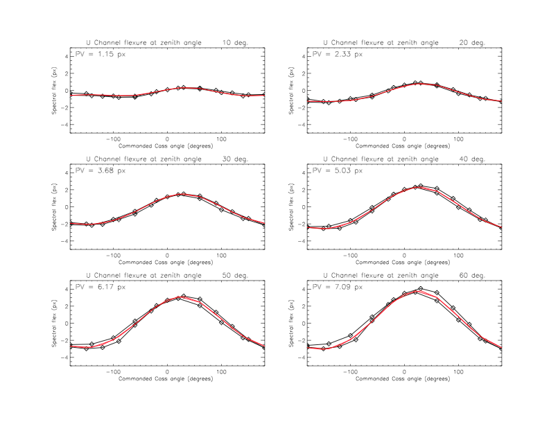
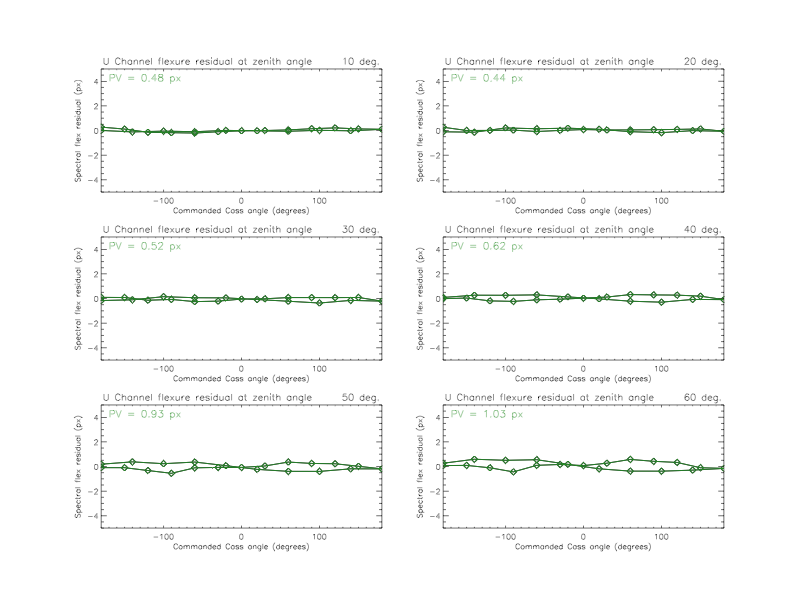
U Channel spectral flexure. Top panel raw and fit (red). Bottom are residuals. See text for further description.
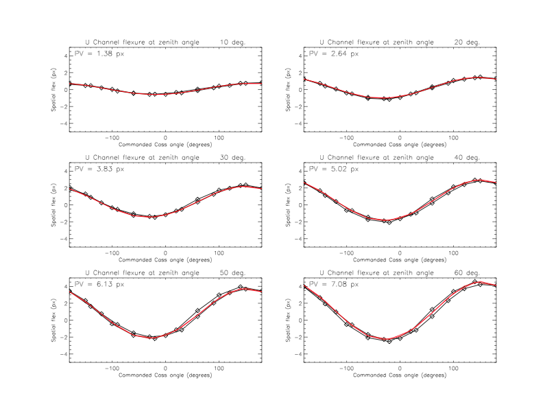
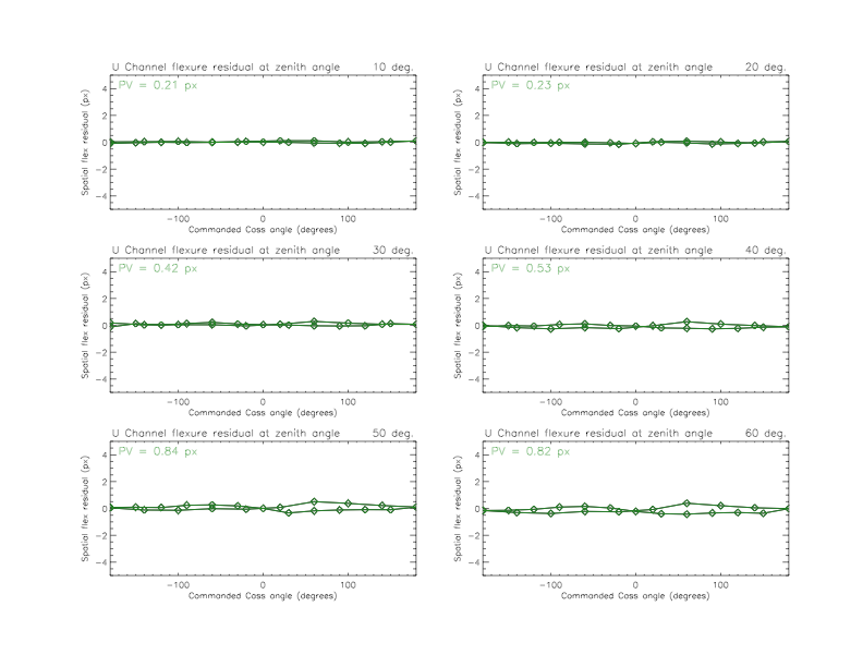
U Channel spatial flexure. Top panel raw and fit (red). Bottom are residuals. See text for further description.
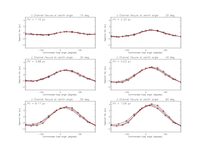
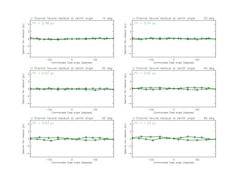
U Channel spectral flexure. Top panel raw and fit (red). Bottom are residuals. See text for further description.
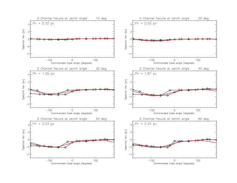
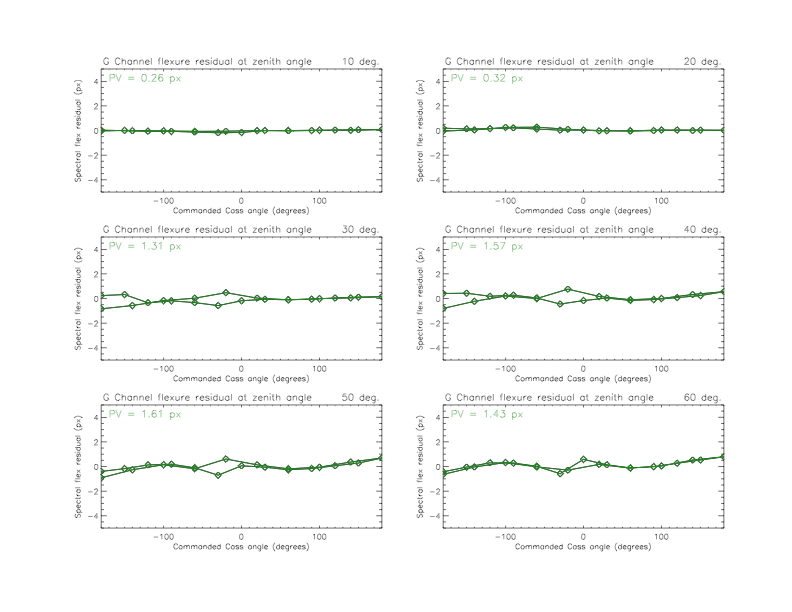
G Channel spectral flexure. Top panel raw and fit (red). Bottom are residuals. See text for further description.
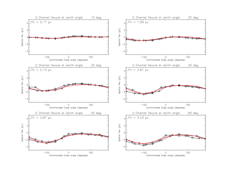
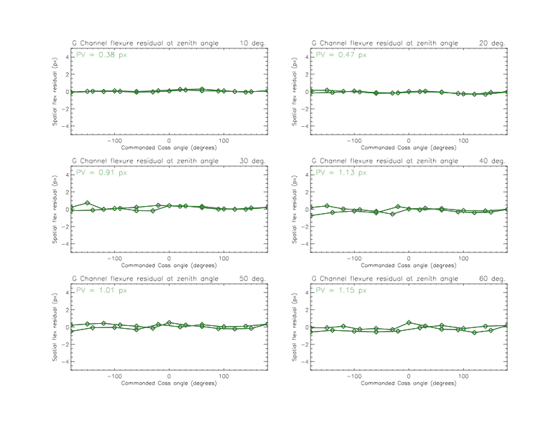
G Channel spatial flexure. Top panel raw and fit (red). Bottom are residuals. See text for further description.
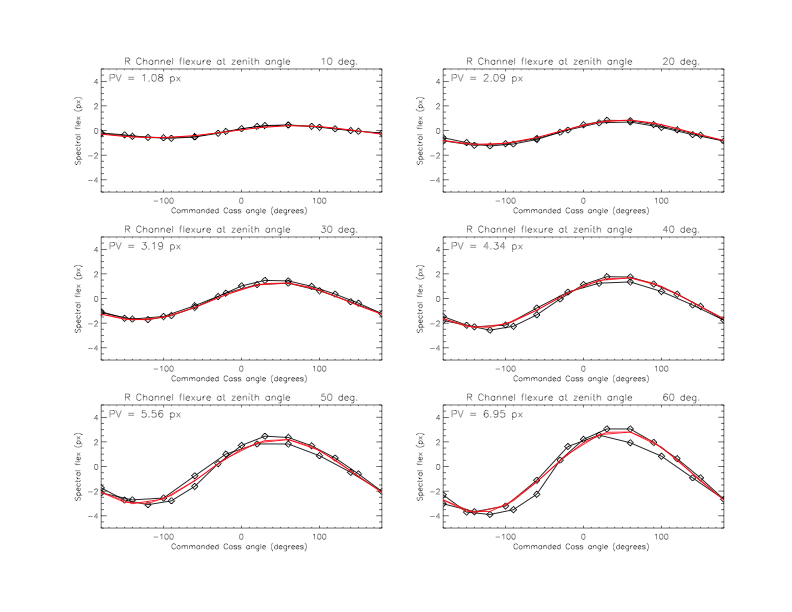
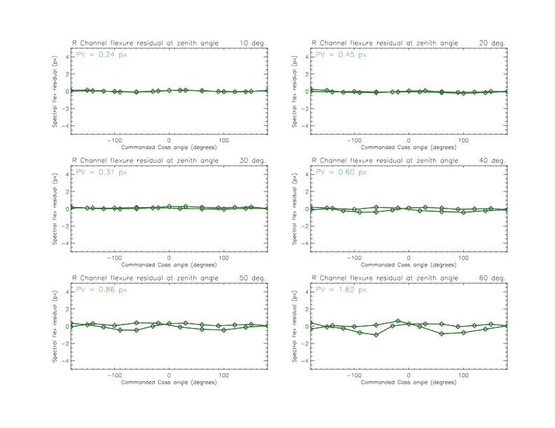
R Channel spectral flexure. Top panel raw and fit (red). Bottom are residuals. See text for further description.
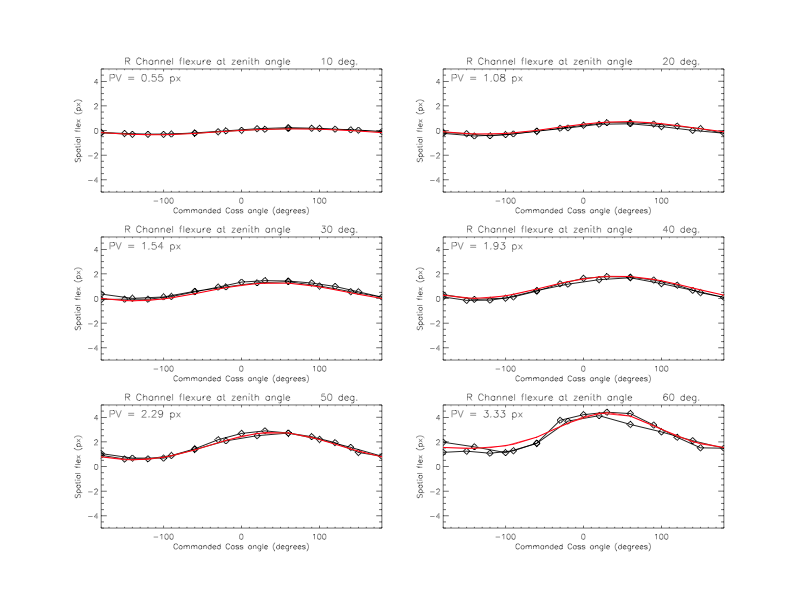
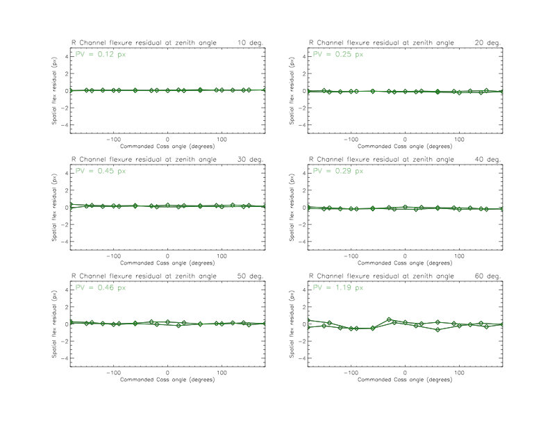
R Channel spatial flexure. Top panel raw and fit (red). Bottom are residuals. See text for further description.
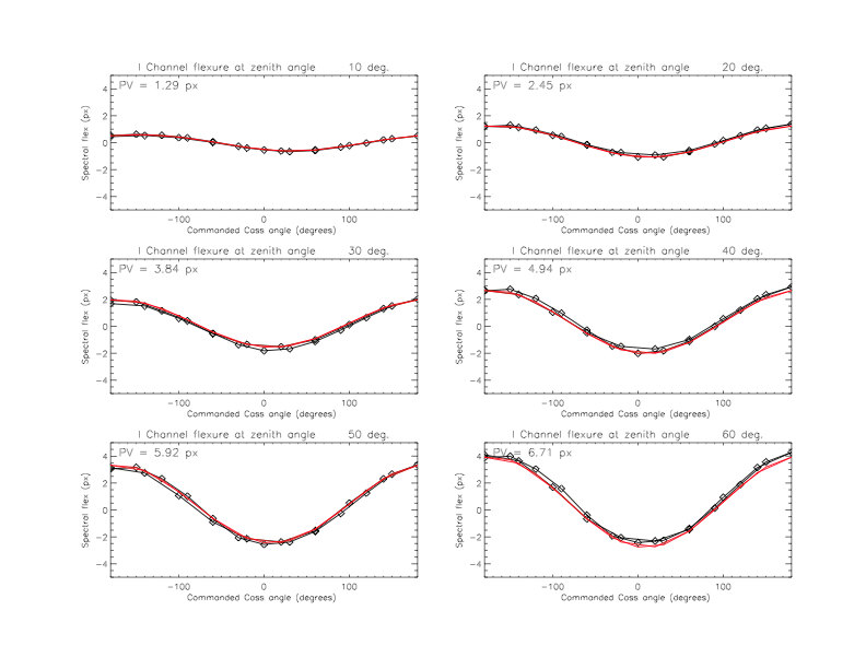
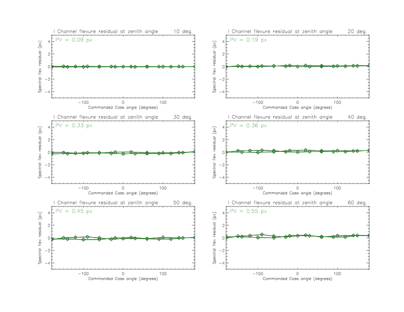
I Channel spectral flexure. Top panel raw and fit (red). Bottom are residuals. See text for further description.
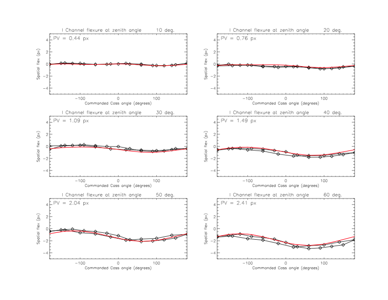
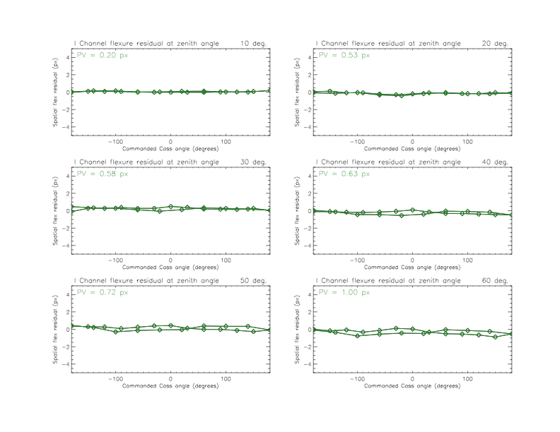
I Channel spectral flexure. Top panel raw and fit (red). Bottom are residuals. See text for further description.
Future work (near term)
Fully validate on sky.
Need to extend model to elevations < 30 degrees after acquisition of additional dark-dome data and investigate an expansion of the model (additional fit terms) to improve the result.
Future work (medium-long term)
Perform scans to understand the nature/location of the observed hysteresis. If possible, consider addressing issue in hardware. Model may be refined based on tracking direction/specific angles where a slip may happen. Note that the 1 pixel level we are seeing corresponds to something in the optical path shifting by a few microns. That may be difficult to track down.
Review night-time sky data on a cadence (quarterly?) to refine model and include temperature dependence. The headers for NGPS data contain pointing information and the necessary commanded flexure compensation information to gauge efficacy of the correction and make any adjustments.
A&G hatch [May 2026]#
The hatch on the A&G system is not operational. We suspect a faulty limit switch.
Intend to repair.
Should not affect observers.
U focus automation [May 2026]#
The U channel focus control electronics were a late change. The stage is operational, but the software interface layer needed to command it from the main ICS is not yet available.
Intend to complete by 2026B
This is a key feature that is missing. Work associated with implementing this will not affect observers.
July 2026 Update
We have not yet addressed this issue. We would still like to.
Improve Spectrograph Focus [May 2026]#
The current performance of the 4 channels is adequate. Due to late installation of the U and G channels (without the benefit of some of the lab alignment tools) and recent retrofit work on R and I channels (and need for slight subsequent realignment) we do see room for improvement.
Desire to complete by 2026B
Turnaround time for an adjustment for a single camera is not long and does not require a thermal cycle. After the adjustment, the spectra may be in a slightly different place on the detector than they are currently, so there will be some pipeline work and extra effort for those programs that wish to combine pre- and post- adjustment data.
As part of this work we would also rotate the U detector to ensure better alignment of the dispersion direction with spectrograph pixels
July 2026 Update
We have not addressed this issue.
NPS power up issue [May 2026]#
There are four network power supplies in the NGPS electronics rack. When the instrument is first powered up, sometimes a fraction of these NPSes do not show up on the network. A power cycle generally resolves the issue. This workaround is not ideal, as all of the hardware attached to the NPS being cycled is cycled as well. Typically only occurs on days when the instrument is installed or removed from the telescope.
We don’t have a clear solution here; some hardware may need to be added to resolve (e.g., NPSes on an external “always-up” network, instead of the private instrument network.
Work on this should be transparent to the observers.
July 2026 Update
We are still working this issue.
Light leaks [May 2026]#
The instrument enclosure is not yet fully light tight. Need to run a in-Cass cage test to locate the issue.
Intend to complete by 2026B
Work on this should be transparent to the observers and should benefit them.
July 2026 Update
We have not addressed this issue. We would like to do so in 2027A. It should not impact observers negatively at all.
G channel read noise#
The G channel read noise is still slightly elevated from where we would like it. After initial deployment of the channel we were seeing 25 e rms which we have subsequently reduced to 8 e rms via minor hardware adjustments. Further reduction will likely involve modification of the DSP code to reduce gain and slow down the readout.
We would like to complete by 2026B
Work on this will require modifications to the detector firmware. This can be done in a manner that does not affect observers (we can always roll back to a previously working version).
July 2026 Update
The read noise is at about 7.3 e rms. This has been accepted by the instrument scientist.
Image slicer rotation#
There appears to be a ~< 1 skew between the slicer spatial direction and dispersion direction. We can correct for this by rotating the image slicer structure on top of the instrument. The gain from implementing this helps with reducing spectral resolution loss when binning.
Considering implementing by 2026B
This work is somewhat invasive and would cause minor pipeline work. Pre-and post work data would need to be reduced differently.
July 2026 Update
Deemed low priority. Should be addressed with a new slicer, when/if that is implemented.
Frame transfer for G, R, and I#
Frame transfer mode has not been tested for G, R, and I. It is not possible for U given the detector. If there are science cases where U is not needed and frame transfer is desired for G, R, and I, we could deploy this.
Intend to wait for U channel upgrade in the next 1-2 yrs to implement frame transfer on other channels
The work would not be invasive or affect observers.
July 2026 Update
This will be completed when the new U and G detectors are being deployed.
Image slicer non-compliance and contamination [May 2026]#
The image slicer optics were accepted without meeting full set of requirements due to schedule and funding constraints. A future slicer upgrade is planned to address the shortcomings.
The instrument does not have an entrance window, we see dust accumulation on the slicer optics. The main slit is unaffected. The optics can be cleaned, but that requires a partial disassembly of the instrument front end (removal of the calibration system). We would like to do this at the same time as installing an instrument window. To accomplish this, need to identify suitable full-bandpass window and may need to revisit guider-IFU confocality alignment.
It is likely that future addition of SIGHT will protect the instrument sufficiently, such that an instrument window is not needed.
This work is invasive and needs to be scheduled. Some risk to the image slicer prisms with mechanical cleaning.
In-Line calibration unit non-compliance [May 2026]#
The initial design called for inline calibration fibers in conjunction with etalon light or arc lamp light. These were intended to help with flexure compensation.
These fibers were installed late and we found they introduced scattered and ghost light into the spectra. Additionally, their spectral signatures change and move with slit width adjustment.
As we are optimistically anticipating a revision of the slicer assembly, we intend to include an optimized version of this spectral reference in that work.
The work to get this going “as is” is not invasive. Any rework would be.
Issue Reporting#
Issue reporting is easy — from any terminal type:
gecko -u 'yourname' -m 'brief descriptive message'
It is important to report all issues as soon as they occur because the time stamps generated by the gecko reporting tool will be used to help diagnose the issue.
Reports will be managed and responded to by the COO software group.